Examples
There are two sample programs to get started with:
LED blinking.
Using the UART to pass data.
Steps For Testing And Cloning The Project
Clone the project
For the LED blinking project:
git clone https://github.com/vicharak-in/LED_BLINKING_DEMO
For the UART demo project:
git clone https://github.com/vicharak-in/UART_RX_TX_DEMO
Before you open the .xml file in the Efinix tool, make sure to follow detailed instructions for setting up Efinity and creating a project.
For comprehensive guidance on setting up Efinity and initiating a project, please consult the Vaaman FPGA Installation Guide: Installation.
Open the .xml file of the project and follow the steps of interface design to set the desired PLL clock.
Note
You do not need to configure GPIO pins in both projects. A .peri.xml file in the repository already includes the project’s input and output pins.
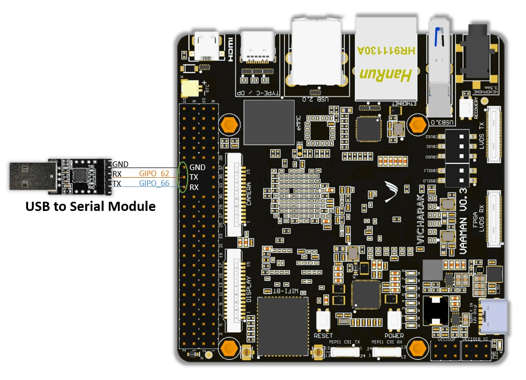
Make sure to establish the correct wiring connections on the Vaaman board as depicted in the image below. To do so, refer to the Download Pinouts.
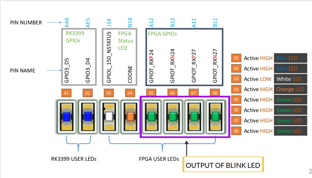
In the led blinking, GPIOR_188 for clock, 4 user leds are used for checking output, that is, GPIOT_RXN27, GPIOT_RXP27, GPIOT_RXP24, and GPIOT_RXN24.
In the UART test, GPIOR_188 sets the clock to 100 MHz and connects the UART RX to the Tx on the Vaaman board, which is GPIOL_62, as well as the UART Tx to the Rx on the Vaaman board, which is GPIOL_66.
Synthesize the design, follow the Efinity programmer steps for loading the bitstream, and run the project on the Vaaman board.
After programming the Vaaman board with the bitstream, the LED BLINK project’s output is immediately displayed through blinking the board’s user LEDs. For UART output, launch GTKTERM, which is the serial communication tool, to view the data being transmitted and reflected in the serial terminal.